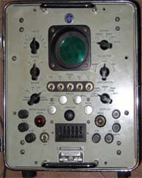
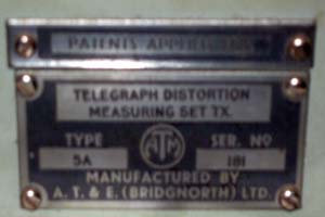
I recently acquired a Telegraph Distortion Measuring Set, manufactured by ATE from UK, model 5A, the TX unit.
Just as a reference, it has a date stated in the relay enclosure of 1951.
If somebody has further information, manual, schematics or a RX unit, please get in contact with me.
What is it?
It is basically an all tube TTY generator, that repeatedly sends a given TTY signal (there are several signal sources available) through the telegraphic line, and displays a comparison between the signal sent and received in a CRT (displaying a ring with two blips, where ideally the two blips should be aligned) effectively showing the distortion of the line for the teletype signals.
The set consists of two similar units, the TX and the RX units. I only have the TX unit, so if somebody has a RX unit, please get in touch with me!
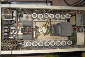
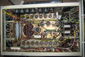
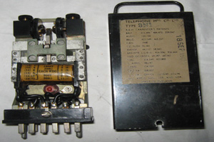
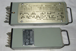
Inside the CRT is a DG7-5 very small. It has 15 tubes, all those that I removed where 12AU7. And the most interesting parts are 2 plugin units, one called the relay and the other the coder. The relay is a very fine and precise polar relay used to detect and latch on transitions, especially considering the widespread usage of double current signals in UK. The relay is pluggable, and I assume a different one could be used for single current, but I don't have the manual to confirm thatAnd the purpose of the coder seems to generate a stream of baudot symbols (kind of a ROM generator ;) I wonder how it does that!), I was unable to open it without destroying it, so I don't know how it works. Also, at the front of the unit there is a plug where I presume you may connect your own coder, perhaps even a paper tape reader?
I reviewed everything, took photos, and then slowly turned it on with my variac. However it seems that there is something wrong, because besides not showing anything on the screen, the power transformer heated too much and I was unable to test further. I guess that once I have some time, I should make more tests, surely this thing can be put into working conditions since it is very well designed, and was extremely clean inside.
Photos
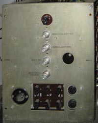
Front | Back |
Top view | Bottom view |
Relay plugin unit | Coder plugin unit (see the baudot code) |
Plaque | |
Links
I have no manuals or schematics, so most of what I write are guesses.
There is a good source here about the generics of the theory but not of this particular model.
Also if you want to see the context, here you have the page of a museum.
I found that at least at the Royal Navy's Museum of Radar and Communications in Hampshire, UK, there is a manual of a similar device (same maker, different model) is available, so if somebody is around who knows! perhaps can give me hand! 
| < Prev | Next > |
|---|


