


It has a very primitive CAT interface, which can be used only to command the radio. (Change VFOs, Frequency, enable/disable functions). It was the first Yaesu transceiver which had a CAT.
Unfortunately the current CAT has several disadvantages:
- It cannot change the mode (a rotary switch makes this nearly impossible, and I don't intend to replace that with a relay bank)
- It cannot report information back (the CAT is unidirectional from PC to TRX)
- As a consequence of 2 if you make a change in the front panel of the TRX, it goes completely unnoticed in the PC.
What can be done then?
- I gave a very deep read to the Tech manual and schematics.
- I opened the unit, and with the Tech manual, identify all the signals I am interested in:
- Display unit 5 wires (Int, K1, K2, K3, K4)
- PO FWD (J27.3)
- PO REV (J27.1)
- ALC (bridge near Q54) (or outside via RCA, but I have this one in use by the ATT)
- AGC (J35.5) (Or outside at the remote connector, but I didn't notice this first)
- IF Width (I intercepted this one)
- IF Shift (I intercepted this one)
- CAT Remote connector (back, 3 wires remote connector)
Decoding the signals
- With the display control lines plugged to a scope, and afterwars the PC via LPT, and using DigiTrace software, I started taking samples and writing everything on a TXT file.
- With that on hand I easily decoded all the information of the display, so now I am able to read the information back into the PC.
- The control signals are basically 13 nibbles of 4 bytes, BCD encoded:
- The first 4 nibbles seem to be a fixed preamble 0A FF
- The next nibble is for VFO-A / VFO-B / MR
- The next nibble is for Clarifier / Split / Lock
- The next 6 nibbles are the main digits
- The final nibble is for the Channel memories
0A FF VFOX XTRA D1 D2 D3 D4 D5 D6 CH
By using DigiTrace (with allowio to access the LPT port in Windows 2000), I was able to setup different information in the TRX display and the give a look to the data channels in DigiTrace. Of course, this can be done in an oscilloscope, as I first did, but it is easier to follow it in DigiTrace.
Here you have an example of the first sample:

Here you can find a few saved dumps of the captured data which can be opened in DigiTrace YaesuCATsamples.zip
Bit Stream
These are the details of the samples on the 5 data channels comming out from the microprocessor into the display unit.
Shown in display Bit stream |
Note: There are a few "x" instead of 0 or 1 in the bitstream, that was because there was a transition shown in DigiTrace, but they were not reals, instead they were a missconfiguration of DigiTrace.Channel 1 is called INT in the Tech Manual, and is in the connector J2020 pin 2It serves as a clock for transferring the nibbles from the CPU to the display driver.The display driver ignores anything it comes until it sees a pulse in the Int line.Keep in mind that the MCU also uses these 4 data lines (K1 .. K4), to scan the keyboard in the display unit. It does that by writting the lines PB0 .. PB2 and verifying from what Kn lines come the data.
- 1 Rst - Reset the display driver
- 2 Int - Interrupt? Signal the display driver that has data on the K lines
- 3 K1 Data line
- 4 K2 Data line
- 5 K3 Data line
- 6 K4 Data line
- 7 PB0
- 8 PB1
- 9 PB2
- 10 500k switch
- 11 PMS button
The connector itself can be viewed right in the front, middle of the "local unit" pcb, you will find it easily because it has many wires and goes to the front right at the back of the display.
Nibble VFOA / VFOB / MR
     A B M
0001 1 0 0
0010 0 0 1
1100 0 1 0

Nibble XTRA: Lock / Split / Clarifier
         Lk Sp Cl
1111     0  0  0
1100 A   0  1  0
1101 d   0  1  0
1110 E/P 0  1  1
0001 1   1  0  0
0000 0   1  1  0
0110 6   1  1  1
2008-06-01 04:27:31
Hardware & Firmware
CAT capabilities
- Split On/Off
- Exchange VFO with Memory (Useless in this case, but available because of the native CAT)
- Write VFO into Memory (Useless in this case, but available because of the native CAT)
- Lock tuning dial
- Change VFO A/B
- Write Memory into VFO
- Up
- Down
- Clarifier On/Off
- Frequency Set (The most important one!)
- Exchange between VFO and Memory (Useless in this case, but available because of the native CAT)
- PTT
- Read transmit status
- Read/Write IF filter Width (write with a DAC)
- Read/Write IF filter Shift (write with a DAC)
- Read AGC (Signal strength)
- Read ALC
- Read Output forward power
- Read Output reverse power
FC-1000 Automatic Antenna Tuner
I also have a FC-1000 Automatic Antenna Tuner. With this, I have as well the following features:
- Read antenna current
- Read match status (matched/not matched)
- Execute antenna tuning (I have to study how to do this because I cannot change the rotary switch to change to CW)
Update 2008-07-10 - It's alive! It breaths!
OK, the thing has been working for some time now, I have achieved almost everything I wanted, except for switching modes (It's just gets too invasive to replace that switch), and controlling the drive level. I yet have to calibrate some stuff like the SWR reading, and to replace the long cable (Yep... I have a 1meter DB25 cable with lots of digital and analog signals alltogether and it still works.).
And finally, I have to polish the firmware and schematics, before posting them here. If you want them just ask. You'll need MPLAB with a fully working C18, because without the procedural abstraction (no available in demo or expired student versions), it just doesn't fit the ROM (yep... It is a LOT of code!).
Update 2008-08-21 - Some photos
Here you have some photos taken throughout the project. I haven't posted any schematic, board layout or firmware yet, because it suffered some modifications on the board afterwards which were not yet included on the Eagle files. Also the firmware is a work on progress, I keep adding stuff all the time.
If you click on the photo you can view it in full size.
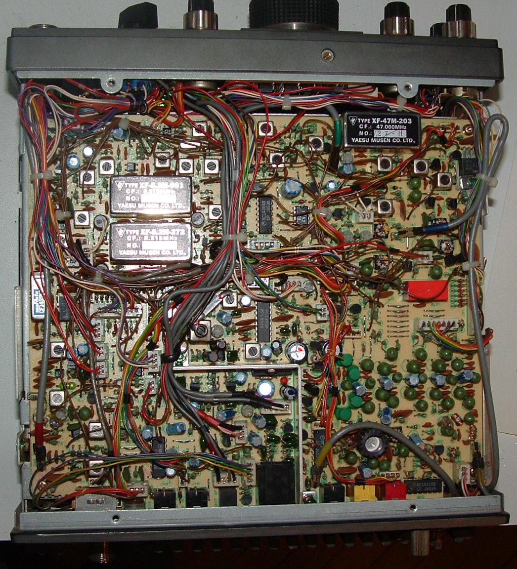
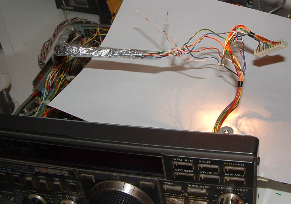
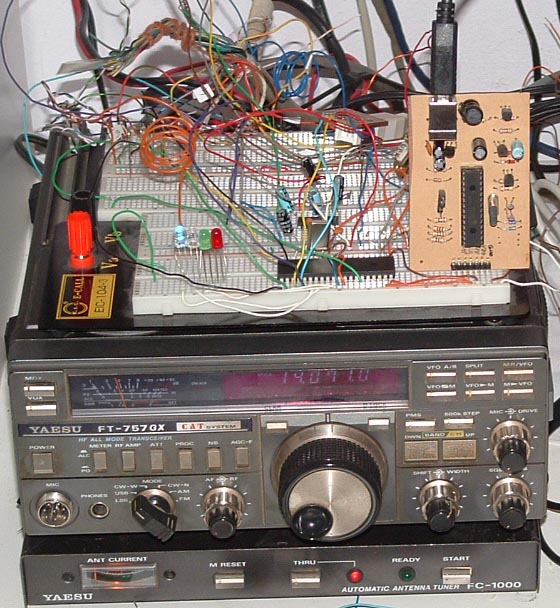
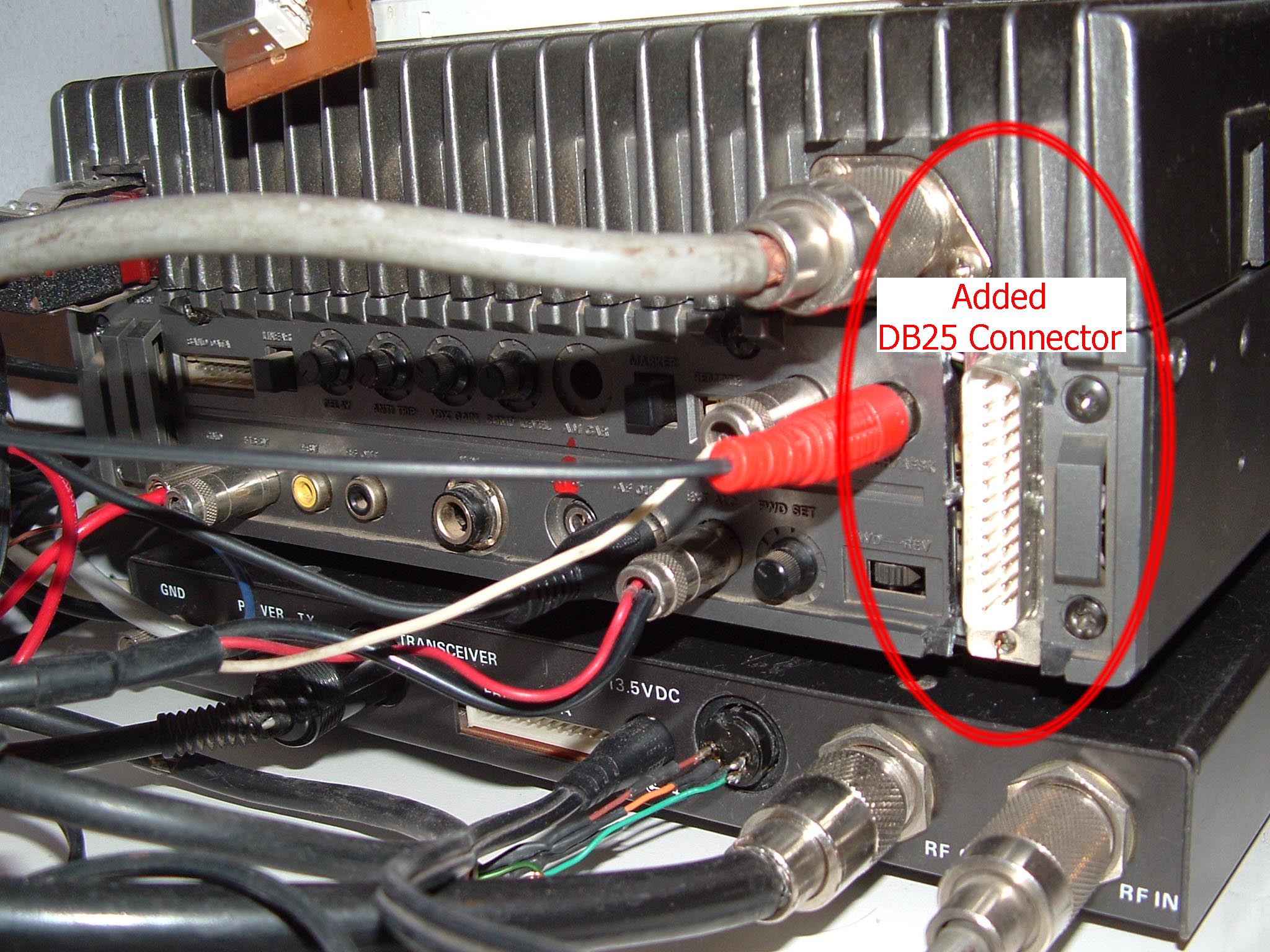
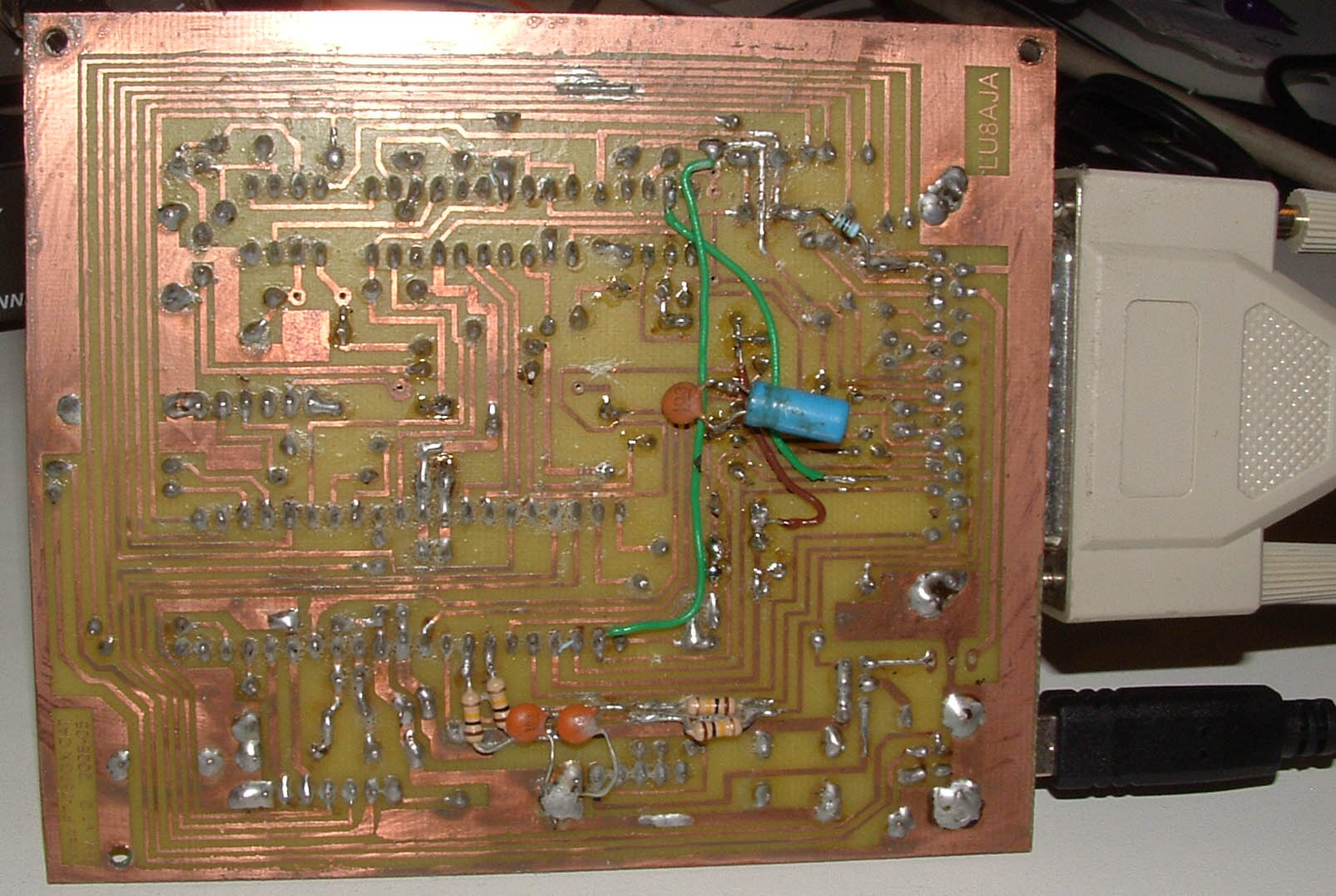
This is the local unit, where the "inteligence" is. Most control, modulation, demodulation, and audio takes place here. Here you will see the microprocessor as well. RF Unit Board This is the RF unit, lots of transistors, coils, etc. Many weak signals as well. Display cable (signals tapped) Here you can see the display lines, which I decode to get the frequency, status, etc. I simply tapped the lines on their way to the connector. Protoboard with experimental desgin Cables flying everywhere, many ICs, leds to debug and my USB PIC programmer. DB 25 Connector Lots of lines with both digital and analog information have to come out of the transceiver. Figuring out a way to take them out, which would not cripple the rig, which would allow the rig to work without the CAT board, and were analog and digital could coexist, was one of the most messy things to achieve. CAT Board (Components side) The board as I currently use it. CAT Board (Copper side) The copper plane of the board. Note that it has suffered quite several important changes after I designed it, to solve different problems that I initially didn't take into consideration. That is the reason I haven't placed the schematics, these changes were not yet updated in the files.Local Unit Board 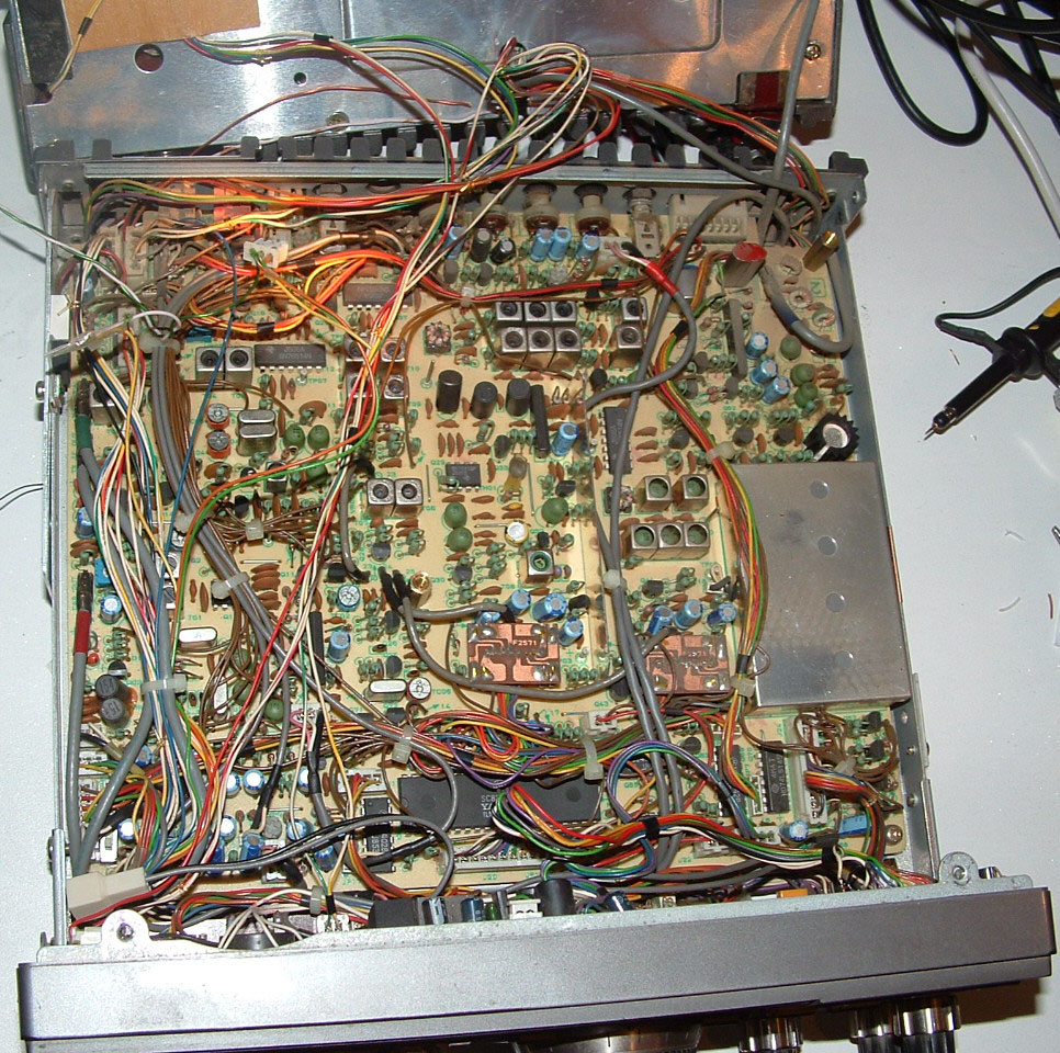

Update 2009-05-25 - Simplified version
I know... so far I haven't posted yet schematics, PCB, or firmware... The reason is that I modified quite some stuff after the PCB was done because there were some design errors at first (and I never updated the schematics or PCB), and another reason is that the DAC I used, was obsolete and sucks... So I should really redo the design and adapt the firmware to keep all the analog capabilities. However, a few hams have emailed me requesting for information, and after all.. all what they wanted was the digital control capabilities, not the analog stuff, so I made a smaller, simplified version, with PCB and FW, that should be working. It has been built and tested by others, so we now know it DOES work ;)
The files are here: YaesuCAT-simplified.v1
 |  |
Also another possible project would be to entirely replace the rig CPU with a new one, and program the CPU control like this project directly in my firmware. However I still don't have the guts to make the replacement, also pin count and available space are real problems. Perhaps one day I will have the guts to do that... who knows.
| < Prev | Next > |
|---|

